DELTA BOT PART 2 : BUILD YOUR OWN!

Hey,

I have recently created a short video presenting what the Delta Bot (or InredBot) can do and how it is programmed, sorry, it is only in polish for now. I may add english subtitles soon 🙂

And I have also decided to share here all the parts for the Delta Bot project. So If you want to create one, or modify my parts and create your own robot design, fell free to do so 🙂 

Here you can find all the parts in .stl format for 3D printing, needed to create it.

InredBot parts.jpg

List of all parts needed:
12 x hinge
6 x rod
3 x arm
3 x block
3 x leg
1 x base
1 x carriage
1 x neck
1 x head
1 x panel
1 x hat
Also you will need:
– Arduino UNO
– 12V battery + buck converter for stable 5V (or any other stable 5V supply),
– three TowerPro SG-5010 servos (or any other similar),
– a fan,
– M4 screws and nuts,
– 3 LEDs,
– 3 push buttons,
– one voltage meter,
– one on/off switch,
– some wires and resistors,
– power drill, 4mm drill bit, 3,4mm drill bit and a M4 tap

– basic soldering skills and you are done.

Here is a very simple program I have written in arduino programming language to control this robot.

If there will be some people interested I can probably do a better tutorial how to assembly you own Delta Bot, but that is all for now, 

Stay Sharp!

The small helper – delta bot part 1


Hey,

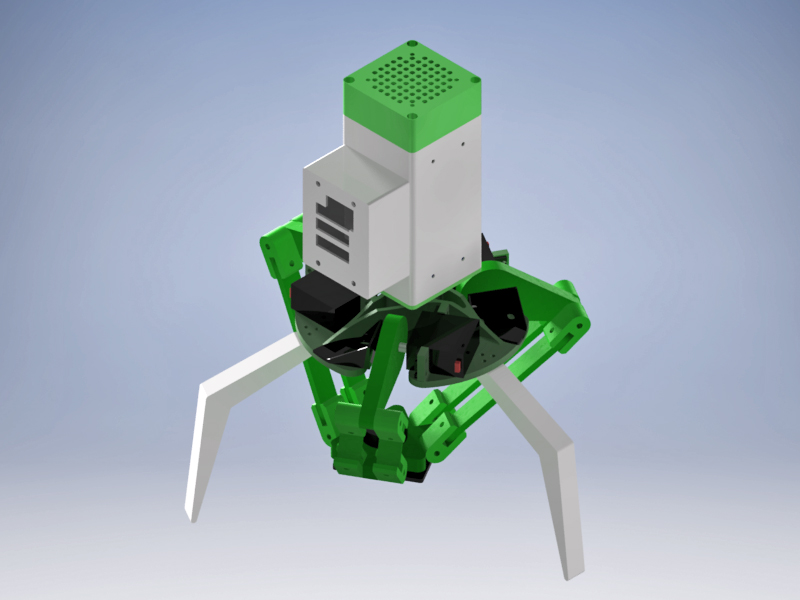
Here is another photostory of one of my projects, a simple delta bot design, created mostly using 3D printing, controlled by an Arduino UNO board. Cheap 5V DC servos were used for controlling the arms. The build started with an 3D model, which was used as a template for creating parts on a 3d printer.

RENDER

All structural moving elements were printed from dark green ABS, M4 screws were used for connecting parts together and also as a rotating axes.

Arms were connected to DC servos using plastic wheels and screws that come as accessories when buying servos. Remaining parts of the delta bot were printed from PLA material, however the white plastic visible on the photos is glow in dark type (fluorescence).

To power up this bot I have created a battery pack consisting of six 18650 Li-ion cells, three in series and two in parallel, it gave me around 12V 4Ah pack. That should be sufficient to power it up for about 2 hours. The case for the battery pack was also 3D printed. And because I didn’t want to put whole three servos current directly through UNO’s board I have used an external 12V to 5V converter, to which servers were connected directly. Also I have added a small 12V fan on the top of the delta bots head mostly to keep the 12V to 5V converter cool.

Small change was made to the construction of the servos, I have soldered 4th wire to the variable potentiometer contact. It allows me to check on what position the servo is at desired moment.

With most of the construction done I started working on a simple pcb board that will allow for some interaction with the bot. It consists of 3 LEDs, 3 push buttons, one voltage meter (so you can know when it needs charging), and one on-off switch.

It is alive!

That is all for this part. In part 2 I’ll present code I wrote to control it and how it is programmed.

Stay sharp!

CNC.. SOMETHING, PART 3: CNC KNIFE GRINDER

Hi!
Due to the end of the semester, and many projects that I had to do and several exams, I was unable to put any new content here, sorry for that. I should have some more free time now.

I continue my construction of a unique CNC machine. The topic of this post has already revealed what it does 🙂 The only thing that’s left is to assembly everything together. Firstly I have connected the numerical controller based on arduino mega (here you can see how the controller is build) to the grinding jig itself.


Then I realized that without any covers on the rails, ball screw and wires it wont last long surrounded by all the steel dust.. I have putted corrugated pipes on the wires and printed simple covers that were later mounted to the table saddle.


Before grinding any knives could be possible the main mounting table needed to be flattened and calibrated. I decided that the best way to achieve this is to grind the table itself on the machine so it will be parallel and flat to the belt.

5 CNC surface grind

A special mounting is needed to grind a knife on this machine. The easiest way to create one is to print it out with a 3D printed, but it is only a temporary solution, because the plastic may melt under the temperature created by the grinding process. The other option is to mill out one from a metal. I have decided to try both options on two folding knives blades models, designed by my brother. During the first tests it turned out that the machine is not as precise as I was hoping, I needed to add some corrections the the G-codes based on a few first grinds.


As expected, 3d printed mounting needed some extra cooling, so I’ll probably use only metal ones in the future. The grinder can grind two smal blades from one side at once under 5 minutes, blade changing proces is pretty easy, all it takes is to unscrew two nuts, change blades and screw on the nuts again, it takes under 1 minute. The machine is not as precise as I wanted it to be, some calibrations are needed for every blade model, even so some hand grinding/finishing is needed. Also it takes alot of time to create a G-code for a single blade model. So it is only worth a while for a small series production.

Overall I am happy with the results. Creation of this grinding jig was a lot of fun, I also belive it is one of a kind machine, I have never seen any machine with moving axes arranged like in this one. The question is: will it be useful? I think I’ll find out soon 🙂

Thats is all for now, stay sharp!

CNC.. SOMETHING, PART 2

Hello!

I’m continuing my creation of a very unique CNC machine, If you haven’t seen the first part check it here!

This part presents you some photos of machining and assembling mechanical parts together.

I have started with machining pre-made linear modules, which I have bought on an auction, to fit in a 1605 chinese ball screws. Slot for a ball screw nut on the middle carriage and slot for cheap ball bearings on the end blocks.

Because I have a 3D printer, I have chosen an easy option and printed out some parts 😉 Mostly stepper motors mountings but also two couplers for stepper motors from solid (100% fill) ABS. And also few spacers and covers.

And then a time has come to use the big boy – plasma cutter! But before I could cut some parts, I needed to divide in half a big sheet metal plate I have bought, so it could easily fit on my CNC plasma cutter table. Most of the cut was done using plasma cutter itself, but because the plate was a little bit too wide, I had to cut it off using disc grinder.

After preparing steel sheet I started cutting out main structural parts for my unique CNC machine. Some of the parts needed extra tweaking with a propane torch and a hammer. Also, below you can see video presenting CNC plasma cutting process.

After all that was done I have started assembling all the mechanical parts together, and mounting it on my old belt grinder.. now I think some of you can guess what this machine will do 🙂

Part 3 coming soon.
Stay Sharp!

Collection Of Works 3: forgotten and new

Hey, here is a quick post, presenting some stuff I have created during last time. I’ll start with some titanium anodized pendants I totally forgot to post before, some of them are game themed (TF2, Fallout, Portal) and some are based on some graphic.

And here are earrings I have made. The cross part is made from anodized titanium and the rest from silver. Unfortunately anodization was wiped out a little bit during sanding process on one of the earrings.

Because my old coolant draining system on my CNC milling machine was leaking I had to create a new one, so I replaced it with a 3D print! It is pretty big part (almost 50cm), so I had to create two separate sections and connect them together. The drain is held on the machine using neodymium magnets, allowing for a quick clean up of the drain. Also on the last picture you can see a strainer for catching up milling chips.

And of course I’m cutting Victorinox scales all the time and even adding some engravings on them 🙂 If you want to see these scales getting finished go check my brothers blog!

Also, together with my brother, we have started working on a project of a friction folder knife – “squirrel”. It is based on one of my brother’s handmade knives (visible here) that he have created few years ago. Here you can see some parts for this project cut out using CNC milling machine (pink G10 handle scales are the prettiest.. right?)

And that is all for now 🙂

Stay Sharp!

CNC.. something, part 1

Hey there,
I have started working on a new CNC machine but I’m not going to tell you what it is for till it’s finished! Of course you can try to guess 🙂 It seems to me that this will be the only machine of its kind. I will present you the pictures of the production process, which may be useful for some DIY constructors 🙂 I will probably have to use 3 of my CNC machines (plasma, mill, 3D printer) to create this beauty!

Part 1 will focus on a CNC controller – electronics and enclosure.

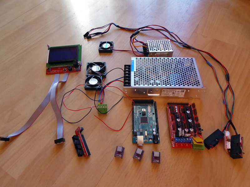
Because this project does not need powerful motors I decided to use cheap stepper motors controlled by an arduino mega board equipped with RAMPS 1,4. I have also bought stepstick based on DRV8825 driver chip. For motors I decided to use 24V 2A secondhand stepper motors bought on an auction. Because arduino board doesn’t like 24V as a supply and I wanted to go full power with these steppers ,I had to use two voltage levels, one for arduino logic, and one for RAMPS. So I bought two separate power supplies, first one 200W 24V, and second 20W 12V. If you want your RAMPS 1,4 to work on 24V you need to make few easy modification to your typical RAMPS board, I have based my modifications on this site. For a display, and SD card reader I have used a “LCD 12864 Smart Controller”. To obtain some zero referencing point I have bought cheap and easy mechanical endstops.

Here are all the elements to drive your stepper motors using G-Code from an SD card:CNC controller partsOn the picture you can also see three 12V fans, one for air circulation in  the enclosure where the electronics is going to be and two for cooling down the stepsticks and whole arduino/RAMPS board.

And here you can see setup for testing 🙂

CNC controller testing

When everything was operating correctly I started working on enclosure for this CNC controller. Of course I decided to use 3D printer I own, because it makes this task a lot easier 😉

Enclosure project began with a 3D model. To fit everything perfectly in a small area I have also created a simple 3D model for every part I want to fit in this housing, keeping in mind the main dimensions and mounting hole locations.

Next step is to print all the parts of enclosure (4 parts in this case: main housing part, rear end cap, front flap, and hinge). Of course there were a few mistakes during printing so you can see some failed parts on 2nd photo 😉 

All parts were printed from PLA plastic. When the whole enclosure was done the last step was to assembly everything, which seemed like an easy task but It turned out to be pretty difficult.. Well next time when designing something I will keep in mind the assembling process 😉 but nevertheless, here is the final CNC controller:

I have only added few things to the basic project, the main power switch (who would thought..) and plastic “glands” to prevent wires from tearing out.

That is all for now 🙂 I hope that I’ll be able to deliver next part soon.

Thanks and Stay Sharp!

3D printing, custom head

Hey

For some time I have been interested in 3D printers, I wasn’t convinced to FDM method of production at first, but after I have seen and held a 3D printed object I noticed it is quite strong and reliable if printed correctly.

Hence I decided to have a 3D printer of my own. Because I didn’t have enough time to create one, together with my bother we bought a second-handed printer. Unfortunately printing head in bought machine wasn’t of good quality, all shabby and temporary, also fans for cooling the print weren’t working and it was difficult to print anything. I think that there was no point to try to repair old head, so I had to create a new one.

I wanted the head to have two separate extruders so I bought premade hot ends, and decided that the whole construction will be created from 10mm thick aluminum (mostly because I had some leftovers of it from other projects), I had to fit my head correctly to dimensions of bought machine so I stared with 3D model. There are no fans and some other details (nuts, screws) on the model, I also used already made NEMA 17 stepper motor model (source).

After the model was finished my CNC milling machine started its job 🙂 Most of the milling was done using 5 mm endmill with two flutes designed for aluminum.

It took few hours to mill the parts, I had to tap few holes, and correct few dimensions (using my flycutter), because it was too tight of a fit to assemble all the parts. I also added a hole on the main construction plate for all the wires.

When all the parts were finished I started assembling the head 🙂

After the main assembly was done I had to wire it, sometimes guessing which wire is for what, original wires were messed up pretty badly. I also added a terminal block for quick and easy connecting/disconnection wires. And here is my actual working printer head:

I know it is not the prettiest, I may add some kind of cover for the wires and terminal block later on.

With the new printing head I started setting up the machine, I tuned the hot ends PID regulators settings, and corrected the zero position. I also leveled the printing table and it was ready for printing.

For my first prints I decided to create some calibration cubes (source file below) with different settings so I can choose the basic print settings for PLA material and I can print some more advanced stuff (even a shelf for my TV PC) 🙂 (source files of used models below)

There is still a lot to correct, I hope my prints will get better eventually 🙂 but for most of my needs this printing precision is enough. Now I have to try printing some stuff from ABS, so probably more printing posts are coming soon 🙂

Stay Sharp!

Source files for used 3D models:

– 25mm calibration cube with empty top
propeller vase
– Standing figure of Alex
– Flame vase 2

.

Comeback after finals

Hi!

I’m sorry that I haven’t posted for a long time now, but at last I have passed all my exams and now I have some free time to spend on my hobby and care a little more about my blog 🙂

For a good start I present you my latest cooperation with my brother (his blog), making custom victorinox swiss army knives scales, some necks knives and folder knive blades designed by him! I have cut out these blanks and scales using my CNC milling machine with 3mm carbide end mill.


Victorinox scales: 4 pairs from Carbon fiber, 2 pairs from two-colour G10 and 4 pairs from titanium! 


Necks and folder blades have been cut out from N690 steel


Finishing these parts is my brother’s task so if you want to see these knives and scales done you should be checking his blog 🙂 That’s all for today, but more will come.

Stay Sharp!

Titanium Sigils

Hi,
I haven’t been posting anything new for a while now. I was busy with my university tasks and had no time to write here, but I’m still making my usual stuff 🙂

I took part in a competition that involved making graphics or pictures of things related to The Talos Principle game. Here is some more info about the competition. Because I’m mostly making my stuff from titanium so I decided to create titanium sigils riddle, similar to the ones you solve during the game. My participation gave me 5th place and the prize: The Talos Principle game copy 🙂 I’m really happy, I didn’t expect to win anything, and created the riddle just for fun, but… I’m not complaining 😉

Some technicals about the riddle:
The sigils are made from 6Al-4V titanium, they are stonewashed and anodized on different colours
Black oak is used as a material for a base plate.
Whole riddle is 118mm by 88mm and 7mm thick.

and some pictures:

Well that’s all for now. I hope I’ll have some more time to present my current projects… there will be some more electronics involved, maybe even an arduino board… who knows 😉

Cheers!